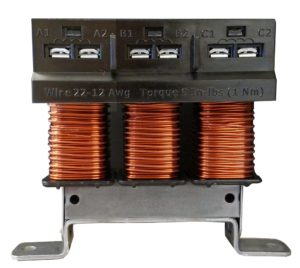
 KDR line reactors are electrical components that help to protect 6-pulse rectifiers and power conversion devices such as variable frequency drives (VFDs). When used in conjunction with a VFD, a KDR line reactor can help reduce harmonics and protect the drive from harmful voltage spikes. KDR line reactors are recommended on the input of each VFD in multiple drive applications.
KDR reactors are constructed with durability in mind and can be used on both the input and output of a VFD. When used on the output of a drive, KDR reactors reduce voltage distortion at the motor terminals, extending the service life and minimizing insulation stress of any motor.
The addition of a KDR Reactor will reduce harmonic content, which reduces the total RMS current, thereby improving the total power factor.
- Nuisance tripping is less common
- Drive uptime is increased
- Power factor is improved
- Limits expensive down-time
- Increases life of drive
- Protects sensitive equipment
TCI offers a wide range of line reactors from 0.25HP to 1500HP. Our newest line reactors, the MA and AA frames, have the smallest footprint in the industry. Every TCI line reactor is manufactured in Wisconsin with high quality materials and is backed by a lifetime warranty for the life of the drive. All of our open panel line reactors are UL Listed.
End of Life Notification
Any KDR Line Reactors with the part number beginning with “KDRA” or KDRULA” has been issued an end of life notice. TCI will stop accepting orders for these products beginning on 12/31/20. These parts have been replaced by the better-performning KDR MA and AA frame reactors. To see detailed drawings and for help with this transition, please click the button below for our KDR MA and AA Frame Transition Page.
MA and AA Frame Reactors
- Smallest footprint available for 0.25 HP – 7.5 HP motors
- The only UL Listed 690 V terminal block reactor on the market
- Available in voltage selections from 208 V to 690 V
- Vertical tool access for easy installation
- Accessory adapter plates available to accommodate different mounting footprint requirements
- New winding capabilities – automated coil winding for faster lead times
The AA frame reactors are a redesign of our standard A frame size. The standard A frame size reactor will still be supported through our Legacy program, however the AA frame offers the same part at a more cost effective price.
Causes of Nuisance Tripping
Input voltage phase unbalance may prevent the drive from performing due to subsequent overcurrent conditions which cause the drive to cease operating. The addition of a KDR Reactor to the input of every drive will help balance the drive input line currents.
A voltage transient, commonly caused by capacitor bank switching (or other issues), sends a current surge into the VFD bus capacitor. The additional current raises bus voltage, thus causing a drive fault (trip). In addition, this overvoltage condition will cause the drive to shut down in order to protect its components. The additional impedance offered by the KDR Line Reactor slows down the current surge, thus reducing the likelihood of the drive tripping offline.
DIN Rail Line Reactor Option
For smaller applications incorporate DIN Rail Drive Reactors to the input and output of PWM drives for easy installation and superior performance:
- Reduce installation time and cost
- Compatible with any 35mm DIN Rail
- Mounts to “Standard Steel High Profile” or “Heavy Duty Steel” DIN Rails
- Reactor mounts horizontally on horizontal DIN Rail
- Improve organization of reactors and their cabling
- RoHS compliant
Lug Kit Part Numbers
| Part Number | DXF | |
|---|---|---|
| SLK10 | LK10 PDF | LK10 DXF |
| SLK11 | LK11 PDF | LK11 DXF |
| SLK12 | LK12 PDF | LK12 DXF |
| SLK13 | LK13 PDF | LK13 DXF |
| SLK14 | LK14 PDF | LK14 DXF |
| SLK15 | LK15 PDF | LK15 DXF |
| SLK16 | LK16 PDF | LK16 DXF |
| SLK17 | LK17 PDF | LK17 DXF |
| SLK18 | LK18 PDF | LK18 DXF |
| SLK20 | LK20 PDF | LK20 DXF |
| SLK21 | LK21 PDF | LK21 DXF |
| SLK17-BB | LK17-BB PDF | LK17-BB DXF |
| SLK18-BB | LK18-BB PDF | LK18-BB DXF |
Impedance Options
The KDR Line Reactor has been designed to provide the best protection for both your drive and your application. KDR Line Reactors are available in two ratings versions, Low “Z” (low impedance, any application where a 3% reactor would be applied) and High “Z” (high impedance, any application where a 5% reactor would be applied). Input impedance can significantly improve drive performance. Select impedance based on the guidelines below:
Use KDR Low “Z” Units For:
Any application where a 3% reactor would be applied. Reduction of nuisance tripping caused by:- Transient voltages caused by capacitor switching
- Line notching
- DC bus overvoltage tripping
- Inverter overcurrent and overvoltage
- Lowering injected percentage of harmonic current
- Improving true power factor
- Reducing cross-talk between drives
- Adding impedance to drives with DC link chokes/reactors when more impedance is desired due to a relatively stiff source
Use KDR High “Z” Units For:
Any application where a 5% reactor would be applied.
KDR High “Z” offers the same superior benefits as Low “Z” plus additional benefits which include:
- Helping prevent drive component damage
- Providing maximum harmonic mitigation without adding capacitance
- Further improving true power factor
- Adding impedance to drives without DC link chokes/reactors when more impedance is desired due to a relatively stiff source
Typical Applications
- Oil and Gas Pumps
- Irrigation Fields, Farms
- Water, Wastewater
- HVAC
- Steel Industry
- Pulp/Paper
- Machining
- Extruders
Single-Phase Applications
KDR Line Reactors can be used in single-phase applications. Please note that the level of impedance will be reduced from three-phase levels.
Contact Technical Support 800-824-8282 for more information.
KDR Specifications
- Impedance Protection: Low “Z” and High “Z”
- System Voltage: 208/240 VAC, 480 VAC, 575/600 VAC, 690 VAC
- Ambient Temperature: 50° C (122° F) – Open; 40° C (104° F) – Enclosed
- Altitude (Maximum): 2,000 meters (6,000 feet) – Derating necessary above 2,000 meters
- Fundamental Frequency: 50/60 Hz
- Short Term Overload Rating: Tolerate 200% rated I for a maximum of 3 minutes
- Agency Approvals: cULus Listed, CE Marked
- Inductance Characteristics: Minimum 95% L at 110% Load; Minimum 80% L at 150% Load
- Input and Output: Available for either the line or load side of a VFD
- Enclosure Options: Open, UL Type 1, NEMA 1, UL Type 3R

