What are Reactors? VFD Protection and Harmonic Mitigation

Quite simply, a 3-phase line reactor is an inductor wired in series between two points in a power system. Reactors are simple electromagnetic devices, some- times referred to as inductors. They consist of a steel core which is constructed of electrical grade steel laminations, and copper wound coils on each leg of a three-phase device. Each leg and coil represents a phase of a three-phase device and is simply wired in series with the variable frequency drive (VFD).
The line reactor provides additional circuit inductance. That inductance is used to derive the line resistance. Impedance is most accurately defined as resistance in ohms but is commonly referenced in terms of percent when combined with the system voltage and line current flowing through the reactor.
That percentage then becomes the common term used to define the level of impedance for each rating of line reactor. That impedance functions to slow the rate of current changes in the line. The greater the current through the reactor, the greater the percentage of applied impedance will be. If a reactor is said to have an impedance rating of 3% or 5%, that means the reactor will apply that specified percent of impedance when the current flowing through the reactor is at the rated current of the device. As the current decreases below the full load current rating of the reactor, the percentage of applied impedance will also decrease proportionately. With that in mind, it is important to avoid oversizing the line reactor for the load current of the application.
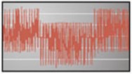
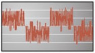
When applied to the input side of a variable frequency drive, the applied impedance of the reactor will work to soften and slow down incoming line voltage distortion such as spikes and surges. This will aid in prevent- ing drive over-voltage faults and damage to the drive input components when line voltage deviations occur. Line disturbances are common on power systems with power factor correction capacitors coming on and offline as well as the fluctuation of high current loads.
Reactors also function to mitigate harmonic currents being drawn by the drive and help block background incoming line voltage harmonics which may hinder the operation of a variable frequency drive. In almost all drive applications, the addition of an input AC line reactor is a low-cost solution for drive protection and harmonic mitigation. See Figures A and B.