Variable Speed Drive with no Harmonic Mitigation
Industry standard variable speed drives, with 6‐pulse diode input rectifiers are the workhorse of industry. They are used primarily for variable speed control of ac induction motors to achieve more efficienct process control and energy savings. Industry standard three‐phase variable speed drives draw harmonic currents from the three phase voltage source. These harmonics can cause overheating and premature failure of power system equipment such as transformers, cables and circuit breakers. The harmonic currents are at higher frequencies than the 60Hz voltage supply.
| Units | Standalone VFD | |
| VFD Power Rating | HP | 500 |
| Input Current | Amps | 544 |
| Fundamental 60Hz Current | Amps | 513 |
| Harmonic Current | Amps | 181 |
| Input Current Distortion | %iTHD | 35.2% |
| Input Voltage Distortion | %vTHD | 4.03% |
Table 1: Summary of standalone 500HP VFD AC input
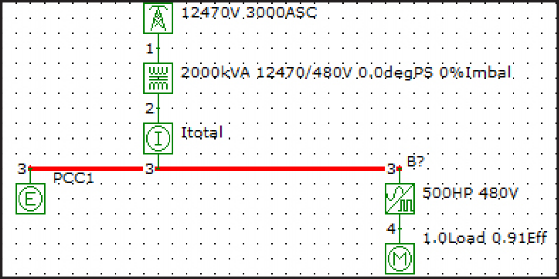
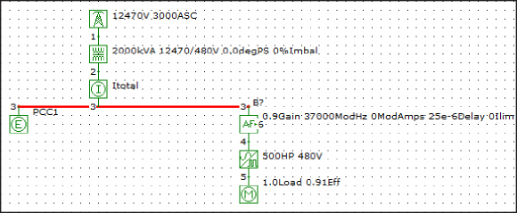
A 480V 3‐phase power system with a typical 500HP VFD with an internal 3% ac input line reactor is shown in Figure 1. The power system transformer feeding the drive is 2000kVA with 5.75% impedance. This system was simulated to characterize the harmonic input voltage and currents caused by the VFD.
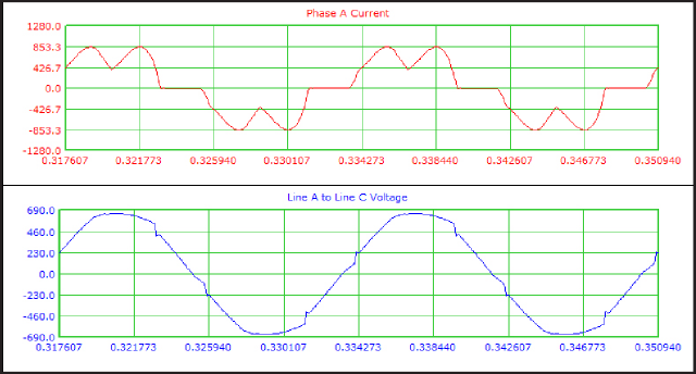
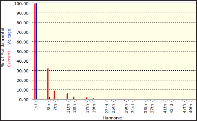
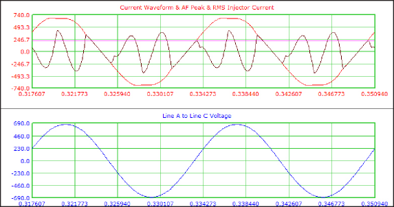
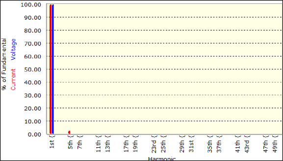
At full load and steady state, the input current and voltage to the 500HP VFD is shown in Figure 2. The input current has a 35% current THD, meaning that harmonic currents are 35% of the 60Hz current. This current distortion in turn produces a voltage distortion across the 2000kVA transformer that powers and may adversely affect other loads on the system. The THD of the voltage in Figure 2 is 4%. A frequency spectrum of the voltage and current is shown in Figure 3. The 5th harmonic current (at 300Hz) is the highest individual harmonic at over 30%.
Variable Speed Drive with an Active Filter
Active filters are highly effective at reducing the harmonic current in the power system to safe levels while allowing the VFD to draw the harmonic currents it needs.
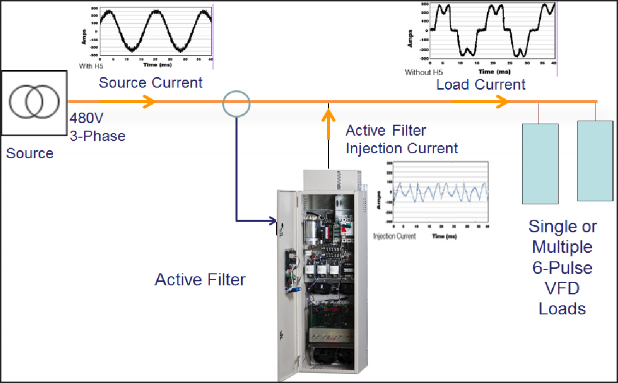
The active filter works by measuring the power system current and injecting the necessary harmonic current to cancel the VFD harmonics. As the filter is an active device is can quickly respond to changes in VFD loading and power system voltage, frequency, unbalance and background voltage distortion conditions. This concept of applying an active filter is illustrated in Figure 4.
Benefits of Active filters to reduce current THD at the input of VFDs are:
- They can be applied to a whole power system, group of loads or on individual standard 6 pulse VFDs
- MCC Compatible
- Can achieve harmonic current reduction to <5% iTHD
- Monitors the bus, injects counter current to cancel out harmonic currents
- Provides Power Factor Correction if necessary
To determine the reduction of harmonic currents achievable with an active filter the 480V 3‐phase power system and 500HP VFD were modeled and analyzed, as shown in Figure 5.
The active filter removes the harmonic currents from the input feed as reflected in the time domain waveforms, shown in Figure 6. The line current and line voltage are near sinusoidal. The current distortion and voltage distortion have been reduced to 3.21% and 0.34% respectively, well under the most stringent IEEE‐519 recommended limits. Figure 6 also shows the harmonic current injected by the active filter, which contains higher frequencies than the source 60 Hz. The frequency spectrum of the filtered source current and voltage is in Figure 7, where the peak current component at the 5th harmonic (300Hz) has been reduced to 2.9%.
| Units | Active Filter And VFD | |
| VFD Power Rating | HP | 500 |
| Input Current | Amps | 496 |
| Fundamental 60Hz Current | Amps | 495 |
| Harmonic Current | Amps | 15.9 |
| Input Current Distortion | %iTHD | 3.21% |
| Input Voltage Distortion | %vTHD | .34% |
| Active Filter Injection Current | Amps | 226 |
Table 2: Summary of Active Filter and 500HP VFD AC Variable Speed Drive with an Active Filter (cont.)
Summary
An active filter is an effective way to filter the harmonic currents required by VFDs and eliminate the harmonic currents and voltages from the AC source. In the case study presented, the active filter reduced the total RMS currents in the source by almost 10% while reducing the current distortion from 35% to 3.2% THD. Resultantly, the voltage distortion was reduced from 4% to under 0.5%.
| Units | Standalone VFD | Active Filter And VFD | |
| VFD Power Rating | HP | 500 | 500 |
| Input Current | Amps | 544 | 496 |
| Fundamental 60Hz Current | Amps | 513 | 495 |
| Harmonic Current | Amps | 181 | 15.9 |
| Input Current Distortion | %iTHD | 35.2% | 3.21% |
| Input Voltage Distortion | %vTHD | 4.03% | .34% |
| Active Filter Injection Current | Amps | — | 226 |
| On a 480V, 60Hz power system with 2000kVA transformer with 5.75% impedance |
Table 3: Summary of 500HP VFD with and without an Active Filter