V1K – Motor Protection Filter

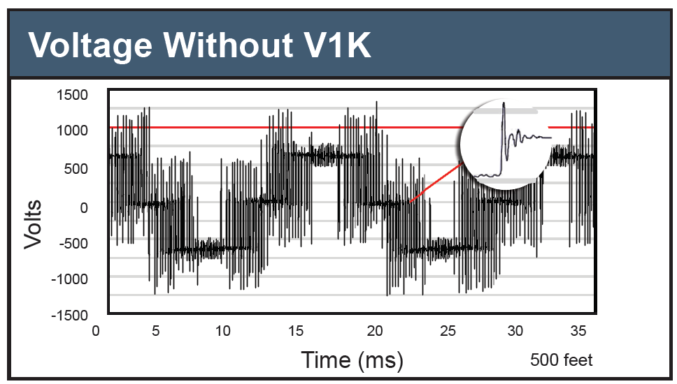
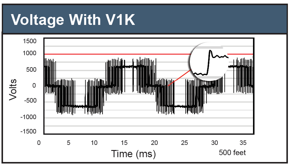
The V1K dV/dt filter provides motor protection by limiting voltage spikes to below 1,000 V for applications with leads lengths from 100 – 1,000 ft. 1

  • Greatly extends the life of the motor and cable
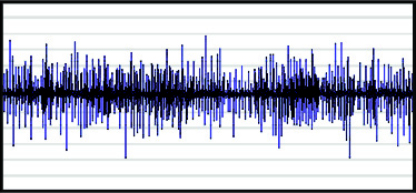
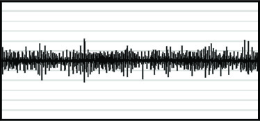
  • 30% reduction in common mode current
  • Optimum dV/dt solution for leads less than 1,000 ft

V1K filters are UL Listed and available in Open, Type 1 and Type 3R packaging configurations.

1Individual applications may vary. Contact TCI to determine the best product for each application.

The V1K has been updated for sizes 2 – 12 Amps. Please see the Product Change Notification for more information.

The V1K field wiring connections will be temporarily updated for parts V1K305_ V1K362_. Please see the Product Change Notification for more information. The Change will occur on shipments after August 24th, 2022, and will end subject to stock availability of standard terminals.

Typical Problems, Superior Solutions with V1K

As Pulse Width Modulated (PWM) Drives are incorporated into various applications and processes, the increased energy savings and decreased maintenance on drives can be offset by increases in motor failures.

The  V1K product family has been designed as an engineered solution for motor failures due to the reflected wave phenomenon.

Reflective Wave Phenomenon

Voltage wave reflection is a function of the voltage rise time (dV/dt) and the length of the motor cables. The impedance on either end of the cable run does not match, causing voltage pulses to be reflected back in the direction from which it arrived. As these reflected waves encounter other waves, their values add, causing higher peak voltage. As wire length or carrier frequency increases, the overshoot peak voltage also increases. Peak Voltages on a 460 V system can reach 1200 to 1600 V, causing rapid breakdown of motor insulation, leading to motor failure. On 575 V systems, the peak voltages can easily reach 2100 V. If this is left uncontrolled, insulation failure will occur.

Mitigate Reflective Wave

By combining a patented dampening circuit with a low pass filter, V1K filters:

  • Increase the voltage rise time (dt out of dV/dt), Slowing pulse transitions thereby reducing dV/dt
  • Prevent voltage spikes from exceeding 1,000 V on 480 V systems
  • Slow pulse transitions, reduce dV/dt
  • Protect motor and cable insulation in PWM Drive applications
 

Reduces Common Mode Motor and Bearing Currents

Common Mode current, which leads to bearing pitting and bearing fluting, is reduced by a minimum of 30%. V1K filters:

  • Dependent on settings, slow down the pulse dV/dt by a factor of 3, reducing the harmful common mode currents
  • Increase bearing life and up-time
  • Reduce common mode noise and currents

Common Mode without V1K

Common Mode with V1K


Multiple Motor Applications: Configuration Guidelines

  • Provide sufficient ventilation.
  • Mount the unit within ten (wire) feet from the drive.
  • Ensure the VFD’s carrier frequency is set to 4 kHz or below and the operating frequency is set to 60 Hz or below.
  • Connect the VFD output leads to the A1, B1, and C1 terminations of the V1k unit. A2, B2, and C2 service the wire to the motor.
  • The length of each motor lead should be less than 500 feet and the sum total of all the leads should be less than 1,500 feet.
  • The total number of motors should be 10 or below.

V1K Specifications

  • Current Range: 208 – 600 V; 2 – 750 amps
  • Power Range: 0.75 – 600 HP
  • Agency Approval: cULus Listed File E116124
  • Enclosures: Open, UL Type 1, and UL Type 3R
  • Efficiency >98%
  • Insulation Rating: 600 V Class
  • Insulation Class: Class H (180°C or better)
  • Ambient Temperature: -40°C to +40°C
  • Maximum Altitude: 2,000 m (6,600 ft) without derating
  • Lead Length: Up to 1,000 ft
  • For use with three phase VFDs operating at 2 kHz – 4 kHz PWM carrier frequency and with a maximum motor cable size necessary to achieve a 5% voltage drop at 1,000 ft
  • Optional thermal switch electrical rating: 120 V/6 A
    • Switch opens on temperature rise
    • 2 A to 12 A standard 195°C trip
    • 2 A to 12 A EX version 160°C trip
    • 16 A to 110 A 160°C trip

V1K Typical Applications

  • Oil and Gas Pumps
  • Irrigation Fields, Farms
  • Water, Wastewater
  • HVAC
  • Pulp, Paper

V1K dV/dt Performance Guarantee

Properly sized and applied, TCI guarantees that the V1K will limit motor terminal peak input voltage to 150% of the bus voltage with a wire lead length of 1,000 feet and a carrier frequency of 4 kHz. Maximum lead length and carrier frequency can vary depending on wire lead type. If a properly selected, installed, and loaded V1K filter fails to meet the guaranteed performance levels, TCI will provide the necessary components or replacement filter at no additional charge. TCI does not take responsibility for additional installation or removal costs, to include, but not limited to, replacement of third party equipment.

Minimum System Requirements for Guarantee – In order to achieve the performance levels as stated in this guarantee, the electrical system must adhere to the following: The V1K must be sized at no more than 110% of the drive output current rating. If the load has a potential for overhauling, the drive must be equipped with braking resistors or other features limiting bus voltage to no more than the level of the peak line voltage. The V1K must be wired no more than 10 feet from the drive.