Adding a Variable Frequency Drive (VFD) to an existing motor application can be a quick and cost-effective way to improve system performance and efficiency. However, if not installed with the proper peripheral devices, this improvement can actually do more harm than good.
VFDs convert the smooth 60Hz sine wave power delivered by the local utility into a Pulse Width Modulated (PWM) waveform approximating a sine wave but at a different voltage and frequency. The desired goal is to be able to vary the speed of a three-phase electric motor. This is accomplished by first converting the delivered AC voltage to DC. This DC voltage is then switched on and off at high frequency and at varying durations to approximate a sine wave. The switching of these devices manifests as fast-changing voltage spikes. In a 480 V system, these spikes can be as high as 1,600 V due to the impedance mismatches on each end of the cabling.
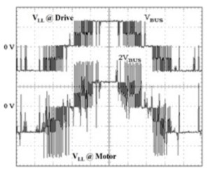
Newer VFD or inverter duty motors are equipped to handle these voltage spikes and in most cases are not adversely affected. However, when using a VFD with an older motor, precautions must be taken to ensure that your motor is not inadvertently damaged. There are several methods readily available to prevent this type of failure.
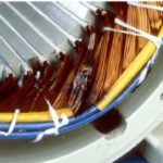
LorNEMA Standard MG1 – Part 30 provides performance standards for general-purpose motors in use with a VFD. It states if operated under usual service conditions, no significant reduction in service life should occur when the peak voltages are limited to 1,000 V and rise times of the peaks are equal to or exceed 2 microseconds. When motors go unprotected in retrofit applications, the line-to-line voltage at the motor can easily see 1,600 V spikes. These spikes can pierce stator insulation which reduces the motor’s resistance to electrical and mechanical degradation and failure.
dV/dt Filter Sine Wave Filter
A dV/dt filter is a dampened low-pass filter that slows the rise time of the PWM pulses thereby reducing the magnitude of the voltage spikes. For applications with cables that are less than 1500 feet in length, the dV/dt filter can reduce voltage spikes to less than 1,000 V.
By dampening the voltage distortion on the output of a VFD and slowing the rise time of voltage spikes through passive filter components, the filter increases the life of the motor.
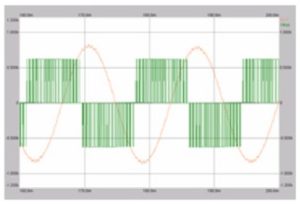
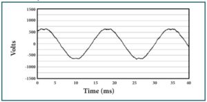
A sine wave filter is a tuned L-C filter designed to smooth the VFD output waveform to near sinusoidal. The filter removes the carrier frequency distortion and harmonics from the drive output pulses and allows the motor to operate the way it was designed. Sine wave filters deliver a near-perfect sinusoidal voltage output to power the motor. Not only will the sine wave filter neutralize leading edge voltage spikes (high dV/dt), it also provides a nearly ideal voltage signal, which thereby increases motor reliability and service life. The following picture shows the pulse width modulation waveform of the drive output and the clean sinusoidal waveform on the output of the sine wave filter.
Votage Without dV/dt Filter
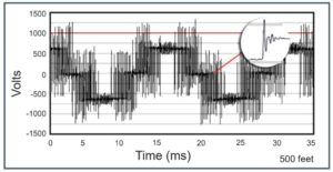
Voltage With dV/dt Filter
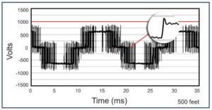
Motor Input Waveform Without L-C Filter
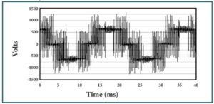
Motor Input Waveform With L-C Filter
As the leader in power quality products, TCI offers solutions for a wide range of motor applications. With TCI’s fast response time, it is now quicker than ever to ensure proper protection on retrofit applications. Want to learn more? For more information on the industry-leading V1K and Motorshield®, please follow the links, or contact a TCI representative at 800-824-8282 to talk about our output motor protection products.